
FDTD Notes
Published:
Learning notes for basics of Lumerical FDTD.
1. Far-field projections
If your structure is periodic, consider using the grating projections. If your structure is not periodic, consider using the far-field projections.
A simple way to understand far field projections is to view them as a decomposition of the near field data using a set of plane waves propagating at different angles as the basis for the decomposition. The end result is that the far field projections functions provide a straightforward, accurate, and numerically efficient method for calculating the EM fields anywhere in the intermediate and far field regions.
It seems that grating projections are the special case (for periodic structures) of far-field projections.
Application cases: fileds known on a plane or a closed surface.
1.2. The mesh order property
The mesh order property governs how overlapping objects are meshed in the simulation. It serves no role for objects which do not overlap.
The mesh order can be set at the material level (in the material database), or the object level (in the object properties).
Materials with a lower mesh order take priority over materials with a higher priority number. Areas that overlap are assigned the material properties of the higher priority material.
3. PML 边界条件
PML 边界基本上被实现为吸收材料,该吸收材料也与周围的材料阻抗匹配,以最大程度地减少反射。 理想的PML边界会产生零反射,但是实际上,由于底层PML方程的离散化,总会有小反射。
3.1 Types
Standard
设计标准轮廓以相对较少的层数提供良好的整体吸收。大量的PML层会大大增加仿真时间,因此建议在考虑任何其他选择之前尝试使用此配置文件。
如果模拟不包含贯穿PML区域的材料边界,则几乎可以肯定,此轮廓将是最明智的选择。
通常,当结构完全延伸通过PML区域时,PML边界性能最佳。每当材料界面穿过PML区域时,可能有必要采用稳定的轮廓。
Stabilized
当材料边界穿过PML区域时,有可能出现数值不稳定性。这些通常表现为PML区域(通常靠近材料界面)内场振幅的局部指数增长。
使用此配置文件可以消除PML区域内可能发生的大多数数值不稳定性,但是,此配置文件需要比标准配置文件更多的PML层数才能实现相同的吸收性能。
稳定的轮廓旨在提供增强的稳定性,但必须增加PML层的数量。
Steep Angle
此配置文件与标准配置文件非常相似,并且意在将PML边界与周期性边界条件结合使用时使用。 它设计用于在光线沿几乎平行于PML边界的方向传播的情况下提供增强的吸收。 在非常粗糙的离散化下(每个波长少于十个点),该轮廓通常比标准轮廓的吸收率低。
Custom
标准的,稳定的和陡峭的侧面轮廓具有固定的PML参数。 自定义配置文件允许用户通过对所有PML参数值的完全控制来进行试验。 自定义配置文件的初始值是标准配置文件的初始值。
3.2 如何使用
- boundary conditions 中的
standard类型适用于在所有边界上使用PML的模拟。 - 如果是周期性的装置,可以将光的衍射,所以选择
steep angle类型。 - PML 边界与光与物质相互作用的平面的距离至少为均匀材料中光波波长的一半。
4. Simulation Region
- Dimension 2D vs 3D:
当仿真区域的某一维度(默认 z 轴)为无限长且均匀,将该维度的截面作为仿真的 2D 区域。设置几何参数时,需要确保该维度上的位置与模拟结构相交。 - Mesh Refinement:
- 一般使用 Conformal Variant0 对非金属材质界面应用保形网格。
- 当有金属时可使用 Conformal Variant1 对金属界面应用保形网格。缺点:网格粗糙导致人工金属模态,因此需要加入额外的收敛性测试。
- 其他选项的鲁棒性不好。
- Simulation time:
较大仿真体积和强共振系统需要较长的仿真时间,以令场通过仿真区域传播且完全衰减。
仿真时间设置过小的可能结果:- 频域监视器的伪影
- 投射谱的 artificial ripples
- The monitors besides the simulation region will not measure any data.
- When the simulation is unstable, smaller time step may be helpful.
- Mesh override region:
- It can be used to define finer mesh on :
- Small structures, e.g. thin layers and gaps
- Plasmonic devices
- The interface between the metal and dieletric materials to have the filed concentrated at the surface
- The thickness of a layer is recommended to includes at least 2 mesh cells.
- The mesh override region contains only an interger number of mesh cells.
- It can be used to define finer mesh on :
- Boundary condition:
- PML: absorb all; more details see
3. PML 边界条件 - metal: perfect metal boundary that reflects all; the most fast option using when the filed will not incounter the boundary
- PMC: perfect magnetic boundary that relects all
- Periodic: used when structure, source, and field are all periodic
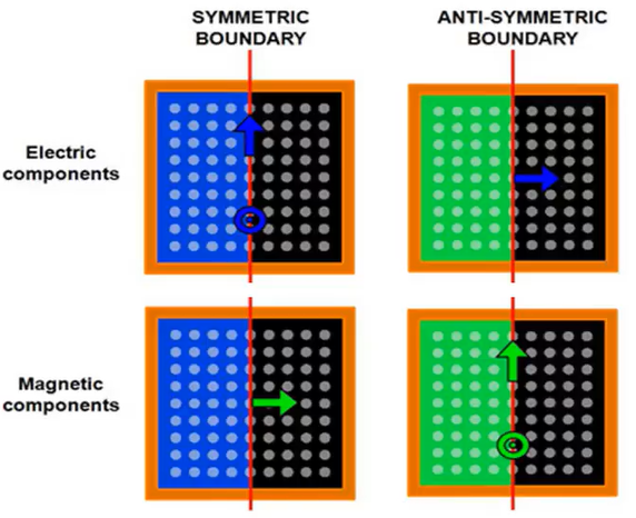
- Symmetry or anti-symmetry: used when structure, source, and field are all symmetric
- Tip: 斜入射平面波必须用 Bloch 边界,斜入射 Guass 光束必须用 PML 边界条件。
- Tip: How to judge symmetry or anti-symmetry? – Test all the possibilities and choose the true one.
经验法则(对照 CAD 彩色视图验证):
 设置方法:
设置方法:
- 2D symmetric structure: Set Symmetry of Anti-symmetry options in
x min bcandy min bc, and set non-symmetry BC (generally PML) inx max bcandy max bc. - 1D symmetric structure (for example, x): Set Symmetry of Anti-symmetry options in both
x min bcandx max bc. - Enable
allow all symmetry on all boundaries.
- 2D symmetric structure: Set Symmetry of Anti-symmetry options in
- PML: absorb all; more details see
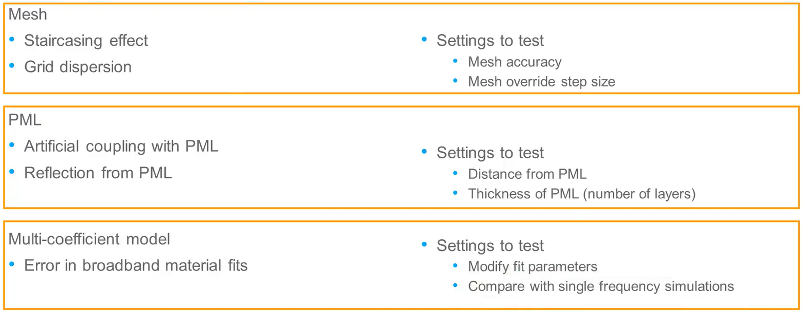
- Mesh accuracy is considered high-accurate at the value 4 or 5.
- If the boundary of PML is placed too close to the structure, there is couping of evanescent fields and PML materials. And sometimes there is reflection fromt the PML.
5. Source
- The fileds measured in the two cells around the source injeciton plane may be unphysical.
- Plane source:
- Bloch/periodic source type is recommended to be used in single frequency simulation. The light at different frequencies will propogate in different angles if the incident angle is normal.
- BFAST source type is recommended to be used in broadband simulation. And for single frequency simulation, more time will be used than Bloch source type.
- Diffracting source type: The source span determines the aperture.
- Tip: The Bloch/periodic or BFAST source will automatically expand to the boundary of simulation region.
- Error: When the non-periodic boundary conditions is used, the Bloch/periodic source at the sides of simulation region will be truncated and the edge effects will appear. In this case, finite-size source (e.g., Guassian source or total-field scattered field source) should be used.
- Error: The BFAST source type is not allowed in non-periodic structure simulation, so the BFAST boundaries will automatically be used and overrite other settings.
经验选择: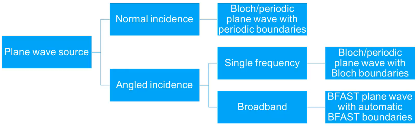
- TFSF (total-field scattered field) source
- Beam source
- Mode source
- Dipole source
6. Monitor
- Using monitors will not increase the simulation time (but increase the memory requirement) except when using a movie monitor.
- Time monitor can be used to check if the simulation time is long enough.
- Use point time monitor can obtain spectrum.
7. Analysis
- Design workflow:
- Start with a coarse mesh
- Convergence testing
- 变精度搜索
- Sources of errors (and corresponding solutions):
- Three factors:
Simulation timeandearly shutoff-auto shutoff min(inEdit FDTD simulation)
- Three factors:
- How to judge whether the simulation stop early?
(One method) Status result of the FDTD solver region:
- 1 - Reached the maximum simulation time
- 2 - Early shut off, reached auto shutoff min threshold
8. Tips
- 要通过收敛性测试实现高精度计算。
- When running,
Force quitis not recommended since it may cause the problem that the license is not released normally.
9. Determine the optimum resource configuration
The key parameter is Processes. See Ref. [1].
Reference
[1] FDTD product reference manual: https://optics.ansys.com/hc/en-us/articles/360033154434-FDTD-product-reference-manual
[2] Python API: https://optics.ansys.com/hc/en-us/sections/360005039073-Automation-API
[3] lsf Language: https://optics.ansys.com/hc/en-us/articles/360034923553
[4] lsf Language Category: https://optics.ansys.com/hc/en-us/articles/360037228834-Lumerical-scripting-language-By-category
[5] ANSYS Forum: https://forum.ansys.com/
[6] Optimum resource configuration: https://optics.ansys.com/hc/en-us/articles/6491711906195-Determine-the-optimum-resource-configuration-to-run-Lumerical-FDTD-simulations
Others resources
[7] PML Boundary condition setting: https://www.cnblogs.com/lihao-bupt/p/13177884.html
[8] FDTD100 Course Notes: https://blog.csdn.net/weixin_45719141/article/details/125373485